
Classroom Presence System, Tap Reader Build
Our own tap reader, a Raspberry Pi 4 with a PN532 NFC HAT, and the circular enclosure it goes into.
Building our own tap reader
Our own reader by the door: today a Raspberry Pi 4 with a PN532 NFC HAT, going into a circular 3D-printed case. The RC522 plan below is kept for reference.
Current build (October 20)
- Reader: a Raspberry Pi 4 with a Waveshare PN532 NFC HAT, plugged straight onto the GPIO header (no loose wires), set to UART mode.
- Cards: S50 (MIFARE Classic 1K) cards, card-sized, read at 13.56 MHz by a short tap.
- Software: the same
reader.py, now with a PN532 mode (READER=pn532). It runs as a service that starts on boot and posts each tap to the OCS presence API. - Tested end to end: tap a card, and the live dashboard shows Present in about 2 seconds.
- Next: the circular enclosure below, then mounting at the door.
We switched from the RC522 board to a PN532 HAT: same 13.56 MHz cards and the same code path, without wiring. The RC522 plan below is kept for reference.
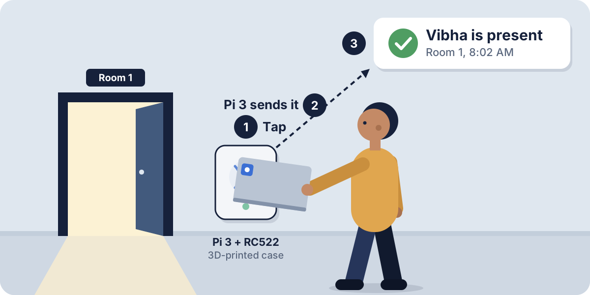
The plan: our own reader by the door, a Pi 3 and an RC522 in a printed case.
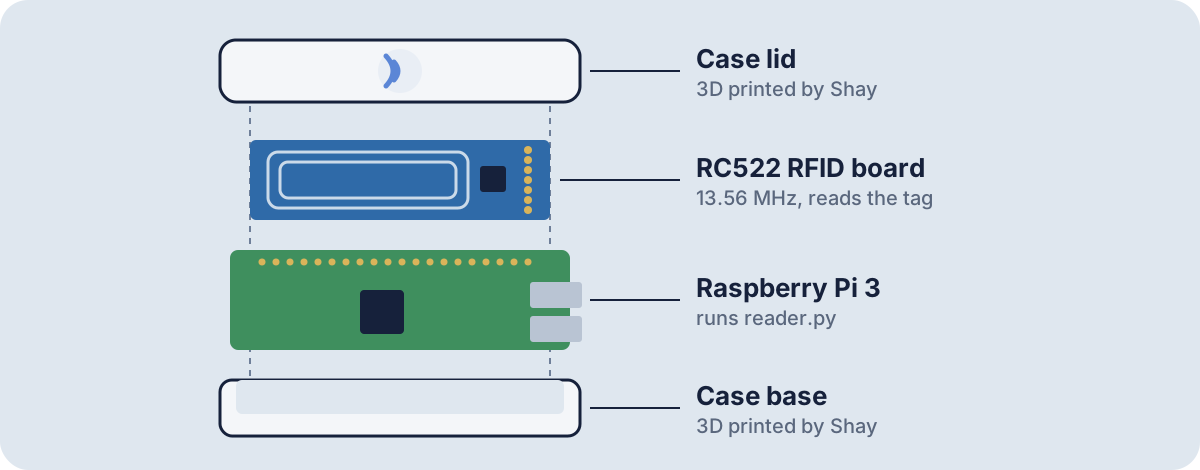
What's inside: lid, RC522, Pi 3, base.
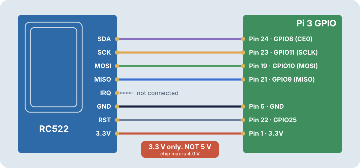
Wiring: SPI0 to the Pi header, the mfrc522 library's default pins. 3.3 V, never 5 V.
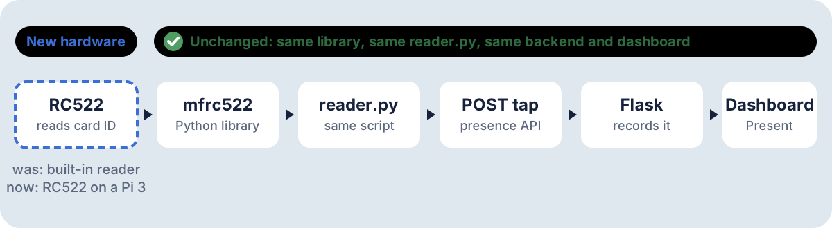
Only the reader hardware changes. Everything after it stays the same.
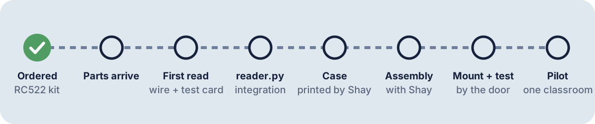
Build timeline: the RC522 is ordered, and everything else comes next.
 Raspberry Pi 3
Have
 RC522 kit · ~$14
Ordered
 Cards + fobs
In the kit
 Case
3D printed
 GPIO board + cables
Have
Photo of the Pi 3, GPIO board and ribbon cable goes here
Parts: most are already here, and the RC522 kit is on order.
Option D: for
- Costs a few dollars
- Works this week
- No code changes
- Same fob IDs as today
Watch out
- Short cable: the Pi sits right behind the reader. Fix: Pi goes in the same case
- Looks like a prototype. Fix: Shay's printed case
Why Option D, from our options doc: cheap, fast, and no code changes.
Enclosure v2: circular, open only at the tap area
Requirements (mentor feedback, issue #15)
- The whole enclosure is circular, like the top of a speaker.
- Closed everywhere except the area directly over the antenna (or thin enough there to read through).
- Obvious where to tap: a raised tap area, or rings that guide the card to the center.
- Power, cables, and ports still reachable with the case closed.
Steps
- Measure the PN532 HAT's antenna area, the Pi 4, its ports, cables, and mounting holes.
- Test how far cards read through PLA at a few thicknesses: fully open top, or a thin closed top.
- Sketch 2–3 options (raised tap area or guide rings) and pick one.
- Model it in CAD with clearance on mating parts for printer shrinkage.
- Print a quick low-infill test piece to check fit, adjust, then do the final print.
- Reliability test with the case on: 10 taps per card, several cards, slightly off-center taps.
The next enclosure, due for N@TM: one circle, one obvious place to tap. Printed with Shay.
Talking points and details
Talking points
Why build our own (Option D)
- Costs a few dollars and can work this week (options doc).
- No code changes:
reader.pyalready reads cards with themfrc522Python library, the standard RC522 library. The fob IDs we've already registered should stay the same. - Mr. Mortensen backed it: he's bringing supplies and ordering the RC522, and Shay is printing a case. Building it ourselves also means we control the hardware and can fix it.
What the RC522 is and how it connects
- An RFID reader board built on NXP's MFRC522 chip. It works at 13.56 MHz and reads MIFARE cards like the S50 (MIFARE Classic 1K) cards and key fobs in the kit.
- It talks to the Pi over SPI: 8 wires to the GPIO header (see the wiring diagram). IRQ isn't used.
- Power is 3.3 V only. The chip's supply range is 2.5–3.6 V and the absolute maximum is 4.0 V, so the Pi's 5 V pins would destroy it.
- SPI has to be switched on in the Pi's settings (
raspi-config→ Interface Options → SPI) before the library can see the board.
Who's doing what
- Mr. Mortensen: supplies, and the RC522 order.
- Shay: prints the case and helps with assembly.
- Us: wiring, software, and testing.
How we'll test it (planned, not done yet)
- First card read: the Pi prints the card's ID. Check it matches the ID already registered for that fob.
- End to end: tap, then the dashboard shows Present. Same checks as the Postman demo.
- Repeated taps: tap many times and count any missed or doubled reads.
- Read distance: measure how far away a tag still reads, both bare and stuck on a laptop.
Open questions
- Network: the Pi 3 will hit the same school-wifi problem as before (devices can't reach my laptop). Options: Ethernet, a phone hotspot, or hosting Flask somewhere both can reach.
- PN532 HAT: do we need it at all, or is the RC522 enough?
- Read range through a laptop or case: laptop bodies (often metal) can weaken 13.56 MHz reads. We need to test where the tag sits.
Sources
- NXP MFRC522 data sheet: supply voltage 2.5–3.6 V (quick reference data), absolute maximum 4.0 V (limiting values). nxp.com/docs/en/data-sheet/MFRC522.pdf
- MFRC522-python library (v0.0.7),
MFRC522.py: SPI bus 0, device 0 (CE0), BOARD pin numbering, reset on pin 22 by default. github.com/pimylifeup/MFRC522-python - Raspberry Pi SPI0 pins: MOSI 19, MISO 21, SCLK 23, CE0 24; 3.3 V on pin 1, GND on pin 6. pinout.xyz/pinout/spi
Not verified on hardware yet: the wiring, the first read, and read range. All of it is planned until the parts arrive.